Status: first article. Not yet printed or assembled; dimensions and steps may change.
Overview
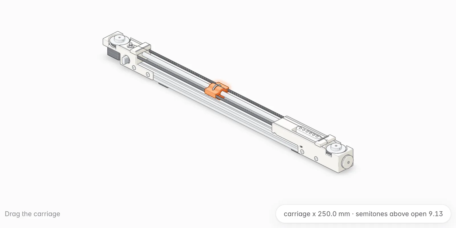
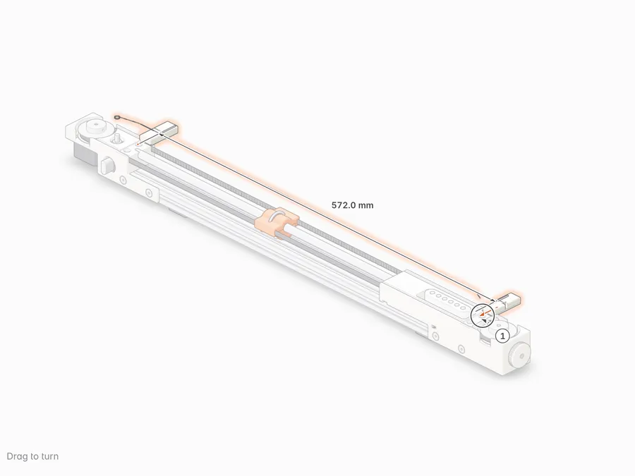
One voice of the monochord: a steel string over a ring fret that a stepper motor moves along a rod.
Drag the carriage; the readout shows semitones above the open string.
- String
- .017 plain steel; 571.5 mm open; about 65 N; about G#3 open
- Fret
- Steel ring, 30 mm, on a 10 mm chrome rod
- Drive
- GT2 belt on 60-tooth pulleys; NEMA 17 pancake stepper (17HS08)
- Range
- About 21 semitones over 388 mm of travel
- Pickup
- Near the bridge; read by the controller
- Exciter
- Space reserved under the string; not yet designed
- Frame
- 2040 aluminium extrusion, cut to 600 mm, ends square
- Printing
- PLA; 0.20 mm layers, 4 walls, 25% infill
- Positions
- X, in mm along the beam from the head-end cut face
Parts
Printed 9
-
 Head block
 -
 Tail block
 -
 Nut cap
 -
 Bridge cap
 -
 Carriage body
 -
 Carriage keel
 -
 Idler sled
 -
 Tension knob
 -
 Race spacer 8 × 1
Bought 17
-
 Rod 10 × 450, hardened chrome
 -
 Bushing RJ4JP-01-10 (or LM10UU)
 -
 Motor 17HS08-1004S pancake
 -
 2× GT2 60T pulley
 -
 Dowel pin 5 × 30
 -
 2× 625ZZ bearing
 -
 Eddaray E-1001 tuner
 -
 Tuner bushing and washer
 -
 Nut rod 3 × 44
 -
 Bridge rod 3 × 32
 -
 String .017 with ball end
 -
 Pickup, single coil
 -
 Endstop module
 -
 2040 beam, 600
 -
 GT2 6 mm belt, about 1.48 m
Fasteners 40
-
 M3 × 25 hex head
 -
 M3 nyloc
 -
 Tuner ear screw
 -
 M3 washer
 -
 12× M5 drop-in T-nut
 -
 4× M3 × 4 socket head
 -
 4× M3 × 14 socket head
 -
 2× M3 × 8 socket head
 -
 2× Pickup screw (supplied)
 -
 4× M5 × 8 socket head
 -
 8× M5 × 6 flat round head
Tools 5
-
 2.5 mm hex key
 -
 3 mm hex key
 -
 4 mm hex key
 -
 Flush cutters
 -
 Phone tuner
Assembly
-
1 Tail block on the bench
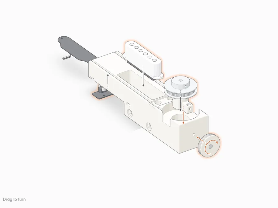
Parts
-
-
-
-
-
-
-
-
-
-
-
-
-
Tools
-
2.5 mm hex key
Steps
-
-
-
-
-
-
-
-
-
-
-
-
-
2 Head block on the bench
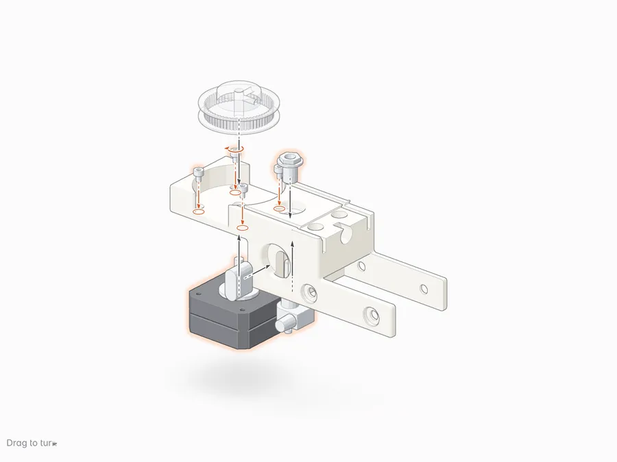
Parts
-
-
-
-
-
-
-
Tools
-
2.5 mm hex key
Steps
-
-
-
-
-
-
-
-
-
-
-
3 Carriage round the ring
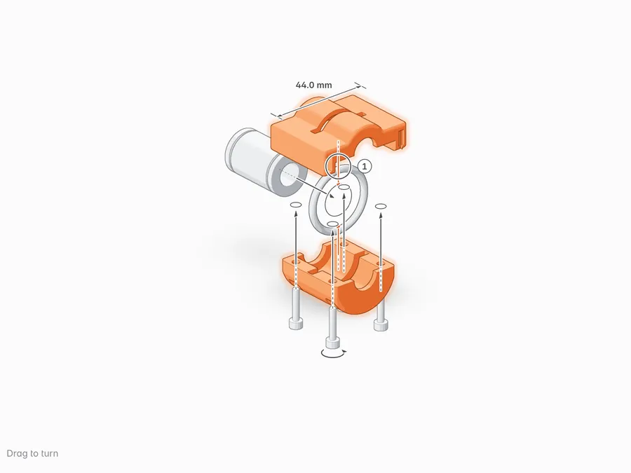
Parts
-
-
-
-
-
Tools
-
2.5 mm hex key
Steps
-
-
-
-
-
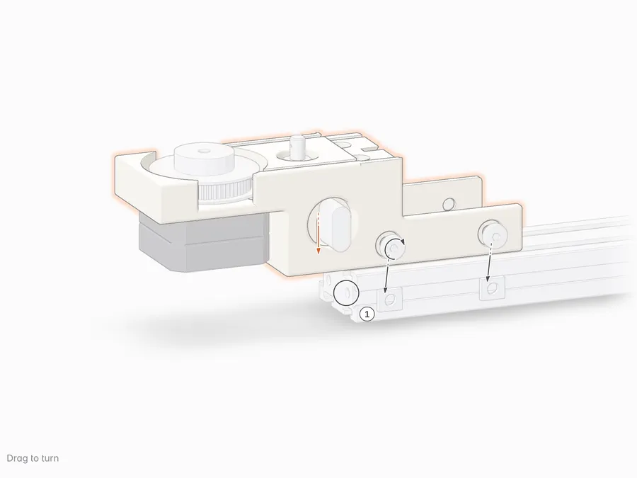
4 Head block onto the beam
Parts
-
-
-
Tools
-
4 mm hex key -
3 mm hex key
Steps
-
-
-
-
-
-
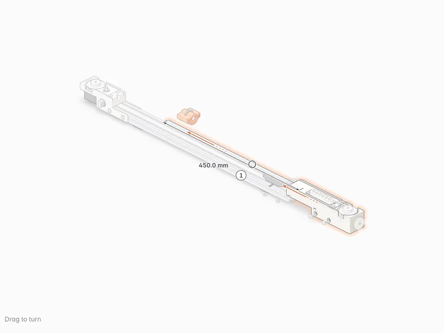
5 Rod and tail block
Parts
-
-
-
-
Tools
-
4 mm hex key -
3 mm hex key
Steps
-
-
-
-
-
-
-
-
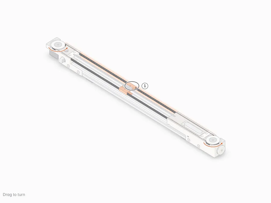
6 Belt round the pulleys
Parts
-
Tools
-
Flush cutters
Steps
-
-
-
-
-
-
-
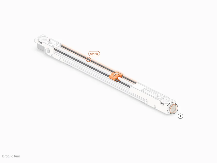
7 Tension by ear
Tools
-
Phone tuner
Steps
-
-
-
-
8 Caps and string
Parts
-
-
-
-
-
-
Steps
-
-
-
-
-
-
-
-
Downloads
First article, not yet printed or fitted.